Content
Data model
Identify some entities
Read the user requirements and look for nouns. The most obvious ones are your best candidates for entities.
Examples: Order, Customer, Address, Order item.
Establish relations between entities
Once you have a couple of entities, find out what are the relationships between them. This includes deciding which entities do have a direct relation and which ones don't, and for each relation specifying its cardinalities.
The most common type of relation is 1:N, where for each 1 instance of a master entity there could be 0 to N instances of detail entity (e.g. each Order has exactly 1 Customer and each Customer may have 0 to N Orders).
Other cardinalities include 1:1 (Order - Address) and 1:1..N (Order - Order item, where each Order must have at least one item). The M:N cardinality is usually a temporary one and over time often evolves into an intermediary entity with two 1:N relations.
List attributes of each entity
Given an entity, name the data items that the system should record for each instance of the entity.
Examples: for entity Order we want to keep Order number, Customer, Due date, Comment, Create time, etc.
Define attribute data types
For each identified attribute define its data type. Data types should ideally be aware of the target database, i.e. if you plan to run on Postgres in production, use data types supported by Postgres.
For attributes representing relations to other entities, the data type is either the related entity (in a logical data model) or the data type of the primary key of the related entity (for physical data model). This might sometimes lead to identifying a new entity.
Examples:
- Order number: varchar(12)
- Due date: date
- Comment: text
- Create time: timestamp
- Customer: Customer (the related entity) - or bigint (the Customer’s primary key data type)
Define attribute statuses
For each attribute define its status.
Is the value of the attribute always present (and the attribute can be made mandatory) or can it be missing sometimes (and the attribute must be optional)? Beware of optional attributes, they should be pretty exceptional, if you find your entity has many optional attributes, you probably have the entity wrong. Most likely it needs to be split into multiple entities.
Is the value of the attribute unique across all the instances of the entity (and the system can and should check for it)? Is it unique and also never changes (and therefore can be used as a natural key of the entity)? Is it a primary key? A foreign key?
Examples:
- Order number: natural key
- Due date: mandatory
- Comment: optional
- Email on Customer: unique
- Id: primary key
Provide example attribute values
Strive to provide sample values for each attribute where possible or meaningful. An example is oftentimes very illustrative and may help the reader understand the attribute better.
Examples:
- Order number: OR-2020-0001
- Due date: 2020-02-20
- Invoice maturity: 30
Define entity lifecycle
Many entities go through different states over time and allow different operations in each of them. The status of an instance may either reflect the development of the corresponding real world entity or a technical aspect of the instance within the system. If the entity has a field named "status", "enabled", "deleted", "sent" or similar, it's a good indication it has a lifecycle. Use the UML state chart diagram to capture the states and transitions between them.
Example: Order status attribute: created, submitted, sent, delivered, invoiced, paid.
Estimate entity volumes
Provide an estimate of the total number of instances of the entity, if applicable, or estimated increase per time period.
Examples:
- Country: 100 total count
- Order: 100 / week
UI: screen mockups
Identify screens
Each entity from the data model will have a couple of screens to display and maintain its data. There will also be additional screens that might not be directly related to any particular entity, e.g. dashboards, reports, etc.
Examples:
- List customers
- Create customer
- Edit customer
- Overdue customers report
Define screen data
Each screen will consist of forms and tables that present data to the user.
For each form define its fields and for each field define its status (read-only, optional, required), type of UI control (plain text, date picker, select, etc.) and an example value.
Similarly, for each table define its columns with example values and if the table is editable also the status and type of control of all the columns. The data should follow the data model where possible.
Examples:
- Customer name: required, plain text: Acme
- Order number: read-only: OR-2020-0001
- Order date: required, date picker: 20. 2. 2020
- Comment: optional, multi-line text
Define screen action buttons and links
Screens contain links and buttons that trigger system functionality and / or navigate between the screens. Specify all such links and buttons to establish navigation between screens and define the ways in which the user can activate system features.
Examples:
- On List customers screen, each row in the table listing the customers is a link to the Customer detail screen
- On Customer detail screen there is the Orders button that links to the List orders screen showing the orders of the customer
- On Customer detail screen there are the Disable and Activate buttons
Describe straightforward system functionality
Specify functionality performed by the system on the user's action in the UI, these are typically buttons or screen loads.
Example: the Disable button on the Customer detail screen sets the Customer Status attribute to "disabled".
Standardize screen flow
Strive to come up with a standardized screen flow for all entities. Rather than inventing new screen flow with every entity, sticking to a standardized one will not only simplify development, but also user experience. The following chart depicts a typical standardized full-fledged CRUDL screen flow for an entity.

Example:
- When you open the “Customers” item from the menu, you see the List customers screen.
- When you select a customer from the list you get to the Customer detail screen.
- There you can perform actions on the customer (typically changing the instance status), delete it or go to the Edit customer screen, etc.
Some entities would have a limited subset of the general screen flow, e.g an immutable entity won’t have the Edit screen, action and delete transitions and might even do without the Detail screen.
API: inbound system interface specification
Identify operations
Identify and name the operations the API provides. You may want to start with CRUDL operations for the system entities.
If the target implementation technology is already decided, embellish each operation with information specific to it. E.g. for REST it might be beneficial to define the verb and URI template of each operation, for SOAP it might be the camel-cased code of the operation, etc.
Define request data structures
For each operation define its request data structure. This comprises identifying the data attributes, their data types and example values, defining required and optional attributes and putting the attributes within an overall structure of the request data (a tree). The request data should follow the data model where possible.
Always include all input data of the operation, for example in REST some data might come in the body while other in the URL (e.g. id of the instance) and the headers (e.g. version of the instance in the "If-Match" header).
Define results
For each operation list its possible outcomes and their corresponding results. An outcome might be the default successful one (happy day), a variant of the successful outcome, a validation error, other types of errors, etc.
For each outcome define its result data structure. List the data attributes, their data types and example values and put them into the overall data structure (tree).
Include all result data for each outcome, for example for REST include the response status code and significant headers (e.g. ETag header for the version of the entity) along with the body.
System functionality: use cases
Brainstorm system actors
An actor is a group of human users with specific goals in the system or an external application that calls the system. Actors usually end up being implemented as user roles.
Examples:
- Sales agent
- Sales manager
- Warehouse clerk
- Delivery
List actor use cases
For each actor, list their use cases in the system. These are user-goal level, black box, system use cases, meaning each use case:
- represents a meaningful business goal that the actor wants to achieve with the system and is able to do so at one time,
- describes the system from the outside, i.e. the system acts as a whole and is not being divided into any components,
- specifies the system functionality, as opposed to either higher-level organizational processes or lower-level design of the system.
Examples:
- Actor Sales agent:
- Create customer
- Edit customer
- Create order
- Submit order
- Actor Sales manager:
- List submitted orders
- Approve order
- Reject order
Define main success scenario
Describe the main successful scenario of interaction of the primary actor with the system.
Each use case (potentially) consists of multiple scenarios how the interaction of the primary actor with the system can unfold, some successful (the use case goal is achieved) and some unsuccessful (the goal is not achieved). The use case format decidedly makes one of them stand out: a successful scenario that is either typical (happens most often) or, sometimes, the simplest one (has the least steps).
The main success scenario is a numbered sequence of steps where a “User” (the primary actor) interacts with the “System”. Each step is a sentence that begins with the word “User” or “System” followed by a verb. (The “user” here is the primary actor, i.e. either a human user using the UI of the “system” or an external application calling the API of the “system”).
The main success scenario is a single scenario, there is no branching there. Alternative scenarios are covered by the extensions. Beware of words “if” or “when” in the main success scenario, they might indicate improper use of branching there.
Example:
Use case: OR-100 Create order
Main success scenario:
- User enters order data.
- User enters order item data.
- System calculates the Item total for each item and Invoice total for the whole order.
- User saves the order.
- System validates the data.
- System creates new Order.
- System sets:
- Order.status = accepted.
- Order.createTime = current timestamp.
- Order.orderNumber = PO-YYYY-SSSSS, where:
- PO is a constant indicating a purchase order
- YYYY is the current year
- SSSSS is a unique sequence number within the current year
- System creates new OrderItem for each order item created by the user.
Identify extensions
Brainstorm all remaining scenarios of the use case, i.e. alternative ways in which the interaction of the user with the system can proceed.
List each one with a reference to the step of the main success scenario to which it relates. Since the steps of the main success scenario are numbered 1., 2., 3. etc., mark each extension with the number of the related step, followed by a letter (a, b, c, etc.) that distinguishes multiple extensions to the same step.
The extension specifies a condition which, when fulfilled, diverts the course of actions from the main success scenario into the extension. The extension condition is formulated as if the word “When” or “If” was at its beginning (although it is not explicitly used there) and is terminated with a colon “:”.
Examples: the above sample use case may have the following extensions:
- 2a. User wants to order more than 1 item:
- 2b. User wants to remove an item from the order:
- 5a. A required field is empty:
- 5b. Due date is in past:
- 5c. Item unit price is < 0:
- 5d. Item quantity is <= 0:
Define extension steps
For each extension specify the steps that take place when the extension’s condition is fulfilled.
Number each extension step with a prefix of the extension itself, followed by the number of the step within the extension, e.g. “2b3.” marks the 3rd. step of the extension 2a.
When an extension step has extensions (variant sub-scenarios) itself, nest these extensions within that step.
Examples:
Use case: CS-100 Create customer
Main success scenario:
- User enters customer data:
- Name
- Tax number
- Address (country, city, street, postal code)
- Phone
- Invoice maturity interval
- System verifies the data.
- System creates new customer.
Extensions:
- 1a. User enters Tax number and loads company data:
- 1a1. System verifies the Tax number is valid.
- 1a1a. Tax number is invalid:
- 1a1a1. System displays error “Tax number is invalid”, but lets the user continue with invalid Tax number.
- 1a1b. Tax number cannot be verified:
- 1a1b1. System displays error “Tax number cannot be verified”.
- 1a1a. Tax number is invalid:
- 1a2. System prefills customer data by the Tax number:
- Name
- Address (country, city, street, postal code)
- 1a1. System verifies the Tax number is valid.
- 2a. Both Email and Phone are empty:
- 2a1. System displays error “Either Email or Phone is required.”
- 2b. Customer with the Tax number already exists:
- 2b1. System displays error “A customer with this Tax number is already registered.” and continues with step 1.
Key takeaways
- Specify the system features iteratively, as they are being developed.
- Use FSD as a tool to understand user requirements and specify them for the subsequent development and testing.
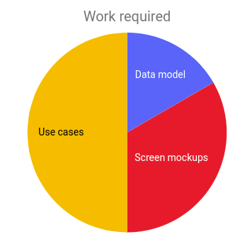
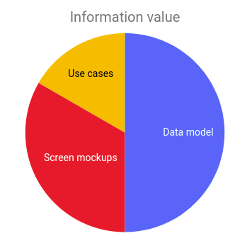
- Target the data model first, then the screen mockups and, finally, use cases where appropriate.
- You are writing the FSD for the readers to read it, keep that in mind and make it as clear and accessible as possible.
- You can tell a great FSD by being actually fun to read.